Start with the Closure, Not the Machine Catalogue
A bottle capping machine can only be selected correctly when the closure and container are treated as one system. The capper must receive each closure in the right orientation, place it without cross-threading or deformation, apply the intended force or torque, and release the finished package without disturbing the bottle. A machine that performs well with one cap may be unsuitable for another cap that appears similar in a product photograph.
Begin the project with approved physical samples. Provide the cap drawing, material, diameter, height, thread or snap geometry, liner, tamper-evident feature and acceptable manufacturing tolerances. For the bottle, provide the neck finish, support-ring dimensions, body shape, material, filled weight and normal dimensional variation. If several suppliers provide bottles or caps, samples should represent the full commercial range rather than a single ideal batch.
Product conditions also affect closure performance. Explain whether the bottle reaches the capper with neck residue, foam, heat, flexibility or internal pressure so the supplier can select suitable application and handling methods.
Match the Capping Principle to the Closure
Screw caps are commonly applied with spindle, chuck or rotary turret systems. Spindle cappers use rotating wheels or belts to tighten the closure as the bottle travels through the machine. They can suit continuous production and a range of container formats when bottle control is stable. Chuck cappers hold the cap with a dedicated head and apply it in a controlled cycle, which can be useful when the closure requires precise engagement. Rotary turret systems distribute bottles among multiple capping heads and are often considered for higher sustained outputs.
Press-on, snap, pump, trigger, cork and crown closures need different handling and application methods. A press-on closure may require controlled vertical force and neck support rather than torque. Pumps and triggers include long dip tubes that must enter the bottle without catching. Crown caps require feeding, positioning and crimping geometry designed for that closure. The proposal should identify the exact capping principle and explain why it matches each approved format.
Avoid selecting by advertised speed alone. Ask how many application stations are proposed, how bottles are stabilized, how cap placement is verified and which change parts each format requires.
Define Torque, Force and Seal Acceptance Clearly
For threaded closures, application torque is an important process variable, but the acceptable value must come from the package design and quality plan. Too little torque can permit leakage or loose caps. Excessive torque can damage threads, distort lightweight bottles, make the package difficult to open or compromise a tamper-evident band. A useful specification describes the target range, measurement method, sampling plan and conditions under which samples will be tested.
Application torque and removal torque are not interchangeable because package materials can relax after capping. Agree on what will be measured during acceptance and routine production, plus how individual head settings will be checked.
Closures applied by force need equally clear acceptance criteria. Define seating height, visible gaps, seal engagement, tamper-evident activation and the conditions that constitute damage. When leak testing or destructive seal checks are required, identify whether they are laboratory tests, offline production checks or automated inline inspections. This prevents a vague requirement such as good sealing from becoming a dispute at commissioning.
Engineer the Cap Feeding and Delivery System
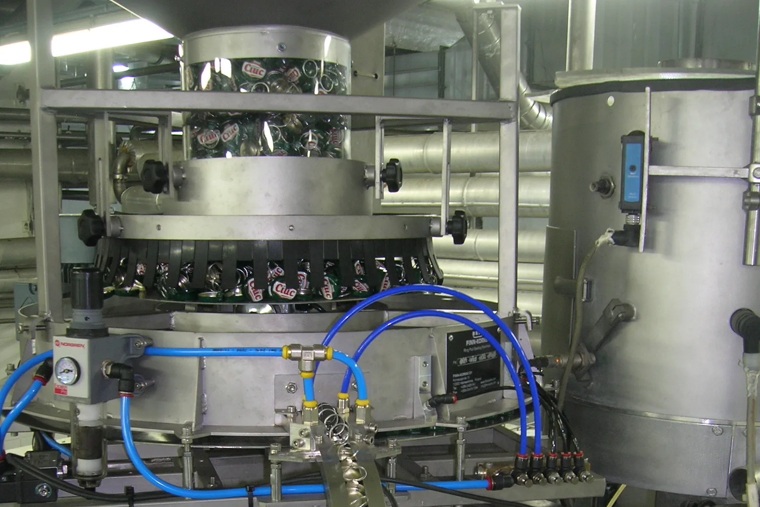
A capable capping head cannot maintain output if closures do not arrive consistently. The feeding system may use a bowl, centrifugal sorter, elevator, hopper, chute or pick-and-place device depending on cap geometry and line speed. It must orient closures without scratching visible surfaces, tangling tamper bands or damaging liners. The supplier should demonstrate the system with production caps, including the variation expected from normal manufacturing lots.
Hopper capacity and loading height affect daily operation. A larger hopper reduces replenishment frequency but may load fragile closures or be difficult to access. Cap elevators or floor-level loading can improve material handling where the production rate justifies them.
The chute between the sorter and capper needs enough accumulation to absorb short interruptions without excessive pressure. Sensors should detect low cap level, blockage and an empty chute. The control logic should define whether the filler slows, stops or finishes its current cycle when caps are unavailable. No-bottle-no-cap and cap-presence checks reduce waste, but they must be integrated with bottle tracking and reject handling.
Integrate Bottle Handling with the Filler and Labeler
Capping performance depends on the condition and spacing of bottles received from the filler. Product on the neck can interfere with cap engagement, while foam or splashing may contaminate the closure area. The filler discharge, conveyor guides and transfer timing should keep bottles upright and provide enough separation for the capper infeed. Unstable containers may require neck handling, side belts, starscrews or dedicated pucks.
Lightweight plastic bottles need particular attention because they can buckle while torque or downward force is applied. The design may require neck support, controlled gripping or a cap head that limits vertical load. Tall or top-heavy packages can rotate during tightening unless side guidance holds them correctly. These issues should be tested with filled bottles because empty samples do not reproduce the weight distribution and structural behavior of production packages.
Downstream equipment also influences the specification. Inspection needs clear bottle spacing and a defined reject point, while labeling requires consistent container presentation. The line controls should state how the filler, capper, inspector and labeler respond to interface faults.
Plan Changeovers, Cleaning and Operator Access
A multi-format capper should be evaluated by its changeover process, not only by the number of compatible formats. Ask the supplier to list every adjustment and change part for the hopper, sorter, chute, cap head, bottle guides and sensors. Tool-less adjustments, position indicators and stored recipes can reduce setup variation, but they do not remove the need for a clear sequence and verification standard.
Estimate changeover frequency and include the expected cleaning work. Product-contact risk may be limited at the capper, yet spills, dust and dropped closures still require accessible surfaces and suitable drainage or collection. The machine should allow safe removal of jammed caps and dropped containers without operators reaching into moving equipment. Guards and interlocks should support normal operation while leaving practical access for approved maintenance procedures.
Store clearly identified format tooling near the line so similar parts are not mixed. Ask which wear parts are used in grippers, chucks, belts, clutches and sensors, and base the maintenance plan on actual operating conditions.
Specify Inspection, Rejection and Production Data
Capping inspection should address the package risks that matter. Typical checks include cap presence, cap height, skewed closure, tamper-band condition and visible seating. Some applications also require torque sampling, leak testing or vision inspection. The best method depends on the closure, bottle material, line speed, label position and quality requirements; a sensor that works on an opaque flat cap may not suit a reflective or irregular closure.
Detection alone is not sufficient. The system should track the failed bottle to a positive reject device, confirm the reject when required and prevent rejected products from being returned unnoticed. Define the response to a full reject bin, failed reject confirmation or repeated capping fault. Production teams may also need fault counts, head-specific trends or interfaces with a line monitoring system.
Keep data requirements proportional to the process. Agree on alarms, production records, communication protocols and data ownership before the electrical design is complete.
Avoid Common Bottle Capper Selection Mistakes
A frequent mistake is approving a capper after a short test with hand-selected components. The trial should use representative bottles and closures, include normal variation and run long enough to reveal feeding or accumulation problems. Another mistake is treating the cap feeder as an accessory. In production, sorting and delivery can become the limiting process even when the capping heads have spare capacity.
Avoid undefined torque statements and theoretical line speeds. Specify measurable acceptance criteria and sustained output with inspection active, then assign responsibility for bottle transfer, fault recovery and acceptance testing across every supplier interface.
Bottle Capping Machine Buyer Checklist
Use one consistent data package when requesting quotations. It helps suppliers select the right capping principle and makes competing proposals easier to compare on the same basis.
- Approved closure drawings, materials, liners, tamper features and production samples.
- Bottle neck finish, body dimensions, material, filled weight and normal variation.
- Product behavior at the capper, including foam, residue, temperature and bottle pressure.
- Required sustained finished output rather than only a mechanical maximum speed.
- Target torque or application force, test method, sample plan and acceptance limits.
- Cap sorting, hopper capacity, loading method, chute accumulation and low-level alarms.
- All bottle and cap formats, changeover frequency, tooling list and recipe requirements.
- Inspection functions, reject logic, production records and communication interfaces.
- Line layout, conveyor height, utilities, access, guarding and maintenance clearance.
- Factory acceptance test materials, run duration, pass criteria and destination market.
Compare Proposals as Complete Closure Systems
The right bottle capping machine is the one that repeatedly feeds, places, tightens or presses, inspects and releases the approved package at the required finished output. A strong proposal makes the closure assumptions visible, identifies change parts, explains bottle support and defines how performance will be tested. It also shows how the capper responds when upstream or downstream equipment stops.
DST can review your closure drawings, bottle samples, product behavior, target output, factory layout and destination market as one line-integration project. Share representative caps and filled-container requirements so the feeding, application, inspection and conveyor interfaces can be evaluated together before the final machine configuration is agreed.
Frequently Asked Questions
Which type of bottle capping machine should I choose?
The choice depends on the closure geometry, bottle stability, required output, application torque or force, changeover range and inspection needs. The proposed method should be tested with production-representative caps and filled bottles.
Why does a bottle capper need actual cap and bottle samples?
Samples reveal dimensional variation, material flexibility, surface finish, tamper-band behavior and how the closure engages the neck. Drawings alone may not show every condition that affects feeding and application.
How should capping torque be specified?
Define the target range, measurement instrument, sample timing, test conditions and pass criteria. Application torque and later removal torque should not be treated as the same measurement.
What should a bottle capping machine acceptance test include?
Use representative closures, bottles and product conditions; run all required line interfaces and inspections; and measure sustained output, cap placement, torque or force, rejects and changeover performance against written criteria.
Discuss Your Filling Project
Share your product, container, target output and destination market. DST will review the application and recommend a practical filling and packaging configuration.
Request a machine recommendation