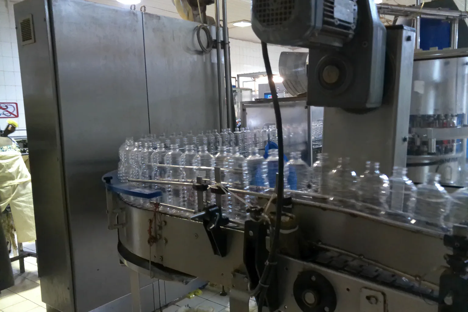
Treat Conveying as Part of the Production Process
Bottle conveyor system design is more than connecting two machines with a belt or chain. The conveying system controls how containers are spaced, accumulated, transferred and presented to each operation. A filler, capper or labeler can meet its individual specification and still deliver poor line output when bottles tip, queue unevenly or arrive at the wrong pitch.
Start with a complete process flow showing every machine, inspection point, reject station, manual task and package format. Define the direction of travel, operating elevation and boundaries between suppliers. The layout should explain who supplies each transfer plate, support rail, sensor, control signal and mechanical connection.
Use the container and closure matrix as a design input. Empty PET bottles, filled glass bottles, tall narrow containers and handled packages behave differently. Weight, base geometry, center of gravity, surface friction and temperature can all change the required support and allowable back pressure.
Define the Real Container Range
Provide drawings and physical samples for every planned bottle. Record overall height and width, base contact area, sidewall stiffness, neck features, cap dimensions and any molded panels that may contact guides. Mark the lightest, tallest, smallest-base and most easily damaged formats because these often govern conveyor behavior.
Specify whether containers are empty, filled, capped, warm, wet or labeled at each section. An empty bottle entering a filler may need neck handling or close side guidance, while a heavy filled bottle may create more accumulation force. Condensation, product residue and label adhesive can also change friction or cleaning needs.
Do not design only from nominal dimensions. Packaging components vary within agreed tolerances, and bottles from different cavities can behave differently. Representative samples allow the integrator to check guide clearances, transfers and accumulation under conditions closer to production.
Plan Transfers Before Adding Conveyor Length
Most handling problems occur where the bottle changes support or speed. Review the infeed and discharge of each machine, including conveyor height, chain type, rail profile and available adjustment. Minimize unsupported gaps and abrupt level changes. Small-diameter or unstable bottles may require dead plates, powered transfers, side belts or other controlled methods.
Curves need enough guidance to maintain orientation without trapping or scuffing containers. A package with a rectangular footprint may rotate in a curve, affecting downstream labeling or inspection. If orientation matters, define the reference feature and the point where it must be established and maintained.
Check changeovers at every transfer. A solution that works for the largest bottle can leave excessive gaps for the smallest one. Record adjustment positions or change parts, and make sure operators can reach them safely without removing unrelated guards.
Use Accumulation to Decouple Short Stops
Accumulation allows one machine to continue briefly when another slows or stops, but it must be sized around a defined operating purpose. State which interruption the buffer should absorb, the expected container rate and the usable conveyor length. Simply adding long conveyor sections does not guarantee useful capacity if bottles cannot enter and leave the buffer smoothly.
Back-pressure accumulation may be acceptable for stable containers, yet excessive force can damage lightweight bottles, mark labels or disturb closures. Low-pressure or pressureless systems can reduce contact but require more control and space. Select the approach around the package and the acceptable contact conditions.
The control strategy should describe how accumulation fills, holds and releases. Avoid repeated stop-start waves that travel upstream and create jams. Sensors should represent usable buffer states, and speed changes should remain within the handling limits of the container.
Coordinate Conveyor Speed and Machine Pitch
A conveyor normally moves faster than the nominal container rate so bottles can separate and recover, but excessive speed can increase instability and noise. Define the required good-output rate by format, then review bottle pitch at the filler, capper, labeler, inspector and packer. Each machine may need a different presentation.
Spacing devices such as timing screws, star wheels, gating cylinders or belts should be included in the line responsibility map. The transition from mass flow to fixed pitch is especially important. Containers must arrive consistently without being crushed by upstream pressure or starved by overly conservative sensor settings.
During trials, measure good output at the end of the agreed line, not only conveyor chain speed. Record micro-stops, tipped containers, manual interventions and faults. These observations reveal whether mechanical handling and control timing support sustained production.
Design Clear Line-Control States
Integrated equipment needs a shared understanding of running, ready, blocked, starved, faulted and emergency-stop conditions. Define which machine sets the line pace and how speed references are distributed. Upstream machines should slow or stop before containers overflow, while downstream machines should restart in a controlled sequence.
Sensor locations and time delays should reflect physical conveyor capacity. A blocked sensor too close to a machine may stop production before useful accumulation is available; a sensor too far away may allow a jam to grow. Document sensor function in the control narrative instead of leaving final tuning entirely to commissioning.
Separate normal production stops from safety functions. Emergency-stop zones, guard circuits and restart permissions should follow the approved safety concept and local requirements. Operators must be able to identify why the line stopped and which action is required before restart.
Integrate Inspection and Reject Handling
Inspection devices need stable, well-spaced containers. Fill-level, cap, label, code or vision checks may require controlled speed, background contrast, lighting and a clear view of the package. Reflective surfaces, clear bottles and condensation can affect sensor performance, so the inspection station should be tested with actual production materials.
Provide enough distance for the system to track a failed container from detection to rejection. Define the reject mechanism, confirmation sensor, reject-bin capacity and response when the bin is full. A detection alarm without reliable physical removal does not protect the finished product stream.
After rejection, the remaining containers should continue without losing spacing or orientation. If manual samples are taken, include a safe sampling point that does not encourage operators to reach across moving equipment.
Account for Hygiene, Cleaning and Maintenance
Conveyor frames, chains, guide rails and support components should suit the product and cleaning environment. Define whether the area is dry-cleaned, wiped, foamed or washed down, and state drainage and material expectations. Product spills should not collect in inaccessible pockets or run toward sensitive equipment.
Maintenance access matters along the entire route. Technicians need to inspect chain wear, sprockets, bearings, drives, sensors and tensioning points. Locate motors and adjustment mechanisms so routine work does not require dismantling large sections of guarding or moving adjacent machines.
Plan lubrication and wear-part management. Where lubrication is used, control application and prevent contamination of containers or labels. Request component identification, recommended spares and maintenance intervals for the supplied configuration.
Review Layout, Access and Future Changes
A conveyor layout must leave space for operators, replenishment, cleaning, maintenance and emergency egress. Avoid creating barriers that force long walking routes or block access to machine doors and change parts. Crossovers or raised sections may help, but they add structural, cleaning and safety considerations.
Reserve future interfaces only where expansion is credible. A removable conveyor section, spare control capacity or defined tie-in point can support planned growth without burdening the first project. Document the assumed future container flow so later equipment does not conflict with the original accumulation logic.
Confirm delivery access and field assembly. Long conveyor frames may need shipping splits, supports and alignment work. The responsibility for final leveling, anchoring, electrical termination and guard completion should be agreed before installation.
Avoid Common Conveyor Integration Mistakes
A frequent mistake is treating conveyor length as automatic accumulation without checking bottle behavior or control logic. Another is designing around one easy bottle while unstable formats are left for site adjustment. Buyers also overlook small mechanical interfaces between different suppliers, creating gaps in responsibility.
Do not accept a line test that only runs machines individually. Integrated testing should include normal starts, stops, starvation, downstream backup, reject handling and format changeover. Finally, avoid undocumented sensor and timer changes during commissioning; capture final settings and the reason for important adjustments.
Bottle Conveyor System Buyer Checklist
Use this checklist when comparing conveyor and packaging-line integration proposals.
- Complete container drawings, samples and condition at each line section.
- Machine elevations, chain types, travel direction and supplier boundaries.
- Transfer method for the smallest, tallest and least stable formats.
- Defined accumulation purpose, usable capacity and back-pressure limits.
- Line speed by format, bottle pitch and spacing-device responsibility.
- Control narrative for ready, running, blocked, starved, fault and restart states.
- Inspection presentation, tracking, reject confirmation and reject-bin response.
- Cleaning method, drainage, lubrication and maintenance access.
- Safety zones, guarding, crossovers and operator access routes.
- Integrated factory and site acceptance tests using representative materials.
Specify the Conveyor as an Integrated System
A reliable bottle conveyor connects mechanical handling, buffer capacity and controls into one testable system. The design should explain how every approved container transfers between machines, how the line responds to interruptions and how operators clean, change and maintain it.
When requesting a proposal, share your product, container range, target output, line scope and destination market. DST can review the conveyor layout together with filling, capping, labeling, inspection and secondary-packaging requirements to propose a practical integrated configuration.
Frequently Asked Questions
How much accumulation does a bottle packaging line need?
There is no universal length. Define the interruption to be absorbed, container rate, usable buffer capacity and bottle contact limits, then size and control the accumulation around that purpose.
Why do bottles tip at conveyor transfers?
Common causes include unsupported gaps, level changes, speed differences, poor guide adjustment, a small bottle base or sudden direction changes. Testing with the least stable production container helps identify the correct transfer method.
Can one conveyor handle several bottle sizes?
A well-defined range can often be handled through adjustable guides, recorded settings and selected change parts. The smallest and least stable formats should be demonstrated during acceptance testing.
Who should control the speed of an integrated packaging line?
The project should define a line-control philosophy identifying the pacing machine, speed references and responses to blocked, starved and fault conditions. Ownership matters more than using one particular control architecture.
Discuss Your Filling Project
Share your product, container, target output and destination market. DST will review the application and recommend a practical filling and packaging configuration.
Request a machine recommendation